Поиск по всей станции
Scope of application
It is widely used in the fields of electronic component sintering, powder material preparation, ceramic process research and development, lithium battery positive and negative electrode material heat treatment, etc. It is especially suitable for precision experiments in laboratories of colleges and universities, research institutes and industrial and mining enterprises.
The split tube furnace is an innovative structural design. Its core feature is the separation of the different functional components of the furnace body into modules that can be operated relatively independently or combined. This design offers significant advantages in terms of improved operational convenience, functional scalability, and an optimized user experience.

Upper and Lower Split Layout: The upper portion houses the heating furnace body, while the lower portion serves as a mobile rack, housing auxiliary equipment such as the vacuum system and gas supply system. This design allows for simple replacement of the lower control unit to meet varying process requirements, greatly enhancing the versatility and flexibility of the equipment.
Independent Heating Furnace Design: The heating furnace body may utilize an open double-layer air-cooled shell structure. A strategically designed air gap and angled design between the shell and the inner chamber effectively maintain the shell surface temperature within a safe range (e.g., below 45°C). The bottom of the furnace body may be equipped with slide rails for rapid temperature adjustment in the active furnace tube area. Modular Integration of Auxiliary Systems: The lower mobile cabinet can integrate various gas control components, such as specialized mass flow meters for hydrogen, nitrogen, argon, and methane, needle valves, and piping, forming a single, independent mobile cabinet for gas control.
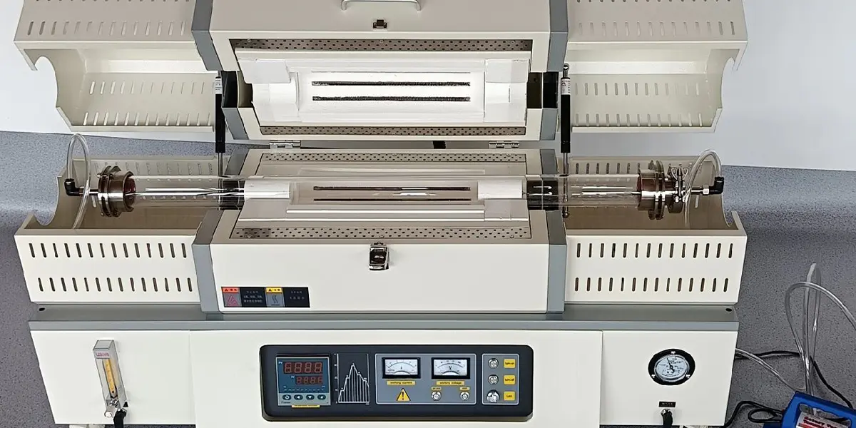
Improved Operational Convenience: The split upper and lower design facilitates operations such as furnace tube replacement and sample placement. For example, the upper heating furnace can be opened with a gas rod. Combined with accurate torque calculation and appropriate opening angle limits, this makes opening the upper furnace cover more labor-saving and safer.
Enhanced Functional Expandability: Because the lower mobile cabinet can be equipped with different control devices (such as vacuum systems and different gas supply systems) based on process requirements, the equipment can adapt to various experimental conditions and process requirements without requiring a complete equipment replacement, reducing costs and improving equipment utilization.
Safety and User-Friendly Design: The split structure optimizes the equipment’s center of gravity and operating height. For example, the optimally positioned furnace operating panel allows for ergonomic operation and improved user experience. Furthermore, the tube protection screens and tube flange supports installed at both ends of the furnace body effectively prevent burns from high temperatures and excessive stress on the tubes.
Key Technical Components and Performance Assurance of Split Tube Furnaces
While inheriting the excellent performance of tube furnaces, the split tube furnace’s unique structure places higher demands on key components.
Highly Insulated and Durable Furnace Chamber: The furnace chamber typically utilizes an imported, high-purity polycrystalline alumina fiber assembly, coated with an imported high-temperature alumina coating. This effectively improves heating efficiency and resists cracking. Heating elements, such as resistance wires, are often arranged in a circular pattern. Stepped seals are used at the contact surface between the upper and lower chambers to prevent flashover, ensuring uniform temperature and a consistent temperature zone.
Fast Temperature Ramp Capability: The sliding rail design at the bottom of the heating furnace, combined with the independent structure of the furnace body, facilitates rapid temperature ramping within the furnace tube area, meeting the requirements for applications requiring rapid temperature changes, such as dynamic sintering. Reliability of the Furnace Tube and Sealing System
High-quality Tube Materials: Split tube furnaces often utilize high-purity double quartz tubes for their tubes, which are corrosion-resistant and can withstand rapid cooling and heating temperatures. Stainless steel flanges seal the ends of the double tubes, and standard vacuum KF connectors effectively ensure a tight seal between the gas path and the reaction environment.
Advanced Temperature Control System: Equipped with advanced temperature control instruments (such as D.2-level), combined with a unique control method and optimized power distribution, this system achieves high-temperature control accuracy and stability, achieving optimal overall stability and improving product heat treatment results.
Flexible Atmosphere Control: The integrated gas flow control system in the lower movable cabinet, combined with the unique furnace tube design (e.g., cooling gas passes through the middle tube, while the reaction gas reacts in the space between the two tubes), enables precise control of the furnace atmosphere.
Application Scenarios and Development Potential of Split Tube Furnaces
Due to their structural features and performance advantages, split tube furnaces are particularly suitable for applications requiring high operational flexibility, process diversity, and experimental precision.
Core Application Areas
Laboratory Dynamic Sintering: Considered an ideal choice for laboratory dynamic sintering applications, it can meet the sintering requirements of materials under different atmospheres and temperature profiles.
New Materials R&D: In laboratories at universities and research institutes, it is used for sintering, melting, and analysis of metals, non-metals, and other compounds. It is particularly suitable for exploratory research that requires frequent changes in experimental conditions and parameters.
Specific Process Experiments: For experiments such as chemical vapor deposition (CVD), which require precise control of the gas atmosphere and temperature profile, the split design facilitates independent control and optimization of gas and temperature parameters.

| Model | Max temperature | Heating zone length | Constant temperature zone length | Power and voltage | Furnace tube size | Dimensions |
| YXG-1200-A1 | 1200℃ | 200mm | 60mm | 1.5kW/AC220V | φ30/50*500mm | 800*340*400mm |
| YXG-1200-A2 | 1200℃ | 440mm | 120mm | 3kW/AC220V | φ30/100*1000mm | 1120*480*530mm |
| YXG-1200II-200 | 1200℃ | 200+200mm | 200mm | 3KW/AC220V | φ30/100*1000mm | 1100*420*560mm |
| YXG-120OIII-200 | 1200℃ | 3*200mm | 3*60mm | 4.5KW/AC220V | φ30/100*1000mm | 1400*420*560mm |
| YXG-1400-400 | 1400℃ | 400mm | 120mm | 5kW/AC220V | φ30/100*1000mm | 1200*500*660mm |
| YXG-140OIl-200 | 1400℃ | 200+200mm | 200mm | 5kW/AC220V | φ30/100*1000mm | 1200*500*660mm |
| YXG-1700-290 | 1700℃ | 290mm | 80mm | 6kW/AC220V | φ30/100*1000mm | 1300*640*870mm |


